


| Part Number(s) (NSID) |
Top View | Type | Pins | MSL Rating | Peak Reflow | RoHS Status |
CAD Symbols | Models | Package Marking Format |
|---|---|---|---|---|---|---|---|---|---|
| LM2597M-12/NOPB LM2597M-12 |
 |
SOIC NARROW | 8 | 1 1 |
260 235 |
Detail | Download | N/A |
NSZXTT 2597 M-12 |
| LM2597M-3.3/NOPB LM2597M-3.3 |
|
SOIC NARROW | 8 | 1 1 |
260 235 |
Detail | Download | N/A |
NSZXTT 2597 M-3.3 |
| LM2597M-5.0/NOPB LM2597M-5.0 |
|
SOIC NARROW | 8 | 1 1 |
260 235 |
Detail | Download | N/A |
NSZXTT 2597 M-5.0 |
| LM2597M-ADJ/NOPB LM2597M-ADJ |
|
SOIC NARROW | 8 | 1 1 |
260 235 |
Detail | Download | N/A |
NSZXTT 2597 M-ADJ |
| LM2597MX-12/NOPB LM2597MX-12 |
|
SOIC NARROW | 8 | 1 1 |
260 235 |
Detail | Download | N/A |
NSZXTT 2597 M-12 |
| LM2597MX-3.3/NOPB LM2597MX-3.3 |
|
SOIC NARROW | 8 | 1 1 |
260 235 |
Detail | Download | N/A |
NSZXTT 2597 M-3.3 |
| LM2597MX-5.0/NOPB LM2597MX-5.0 |
|
SOIC NARROW | 8 | 1 1 |
260 235 |
Detail | Download | N/A |
NSZXTT 2597 M-5.0 |
| LM2597MX-ADJ/NOPB |
|
SOIC NARROW | 8 | 1 | 260 | Detail | Download | N/A |
NSZXTT 2597 M-ADJ |
| LM2597N-12/NOPB LM2597N-12 |
 |
MDIP | 8 | 1 1 |
NA NA |
Detail | Download | N/A |
NSUZXYTTE# LM2597N -12 P+ |
| LM2597N-3.3/NOPB LM2597N-3.3 |
|
MDIP | 8 | 1 1 |
NA NA |
Detail | Download | N/A |
NSUZXYTTE# LM2597N -3.3 P+ |
| LM2597N-5.0/NOPB LM2597N-5.0 |
|
MDIP | 8 | 1 1 |
NA NA |
Detail | Download | N/A |
NSUZXYTTE# LM2597N -5.0 P+ |
| LM2597N-ADJ/NOPB LM2597N-ADJ |
|
MDIP | 8 | 1 1 |
NA NA |
Detail | Download | N/A |
NSUZXYTTE# LM2597N -ADJ P+ |
PDF
Description
The LM2597/LM2597HV series of regulators are monolithic integrated circuits that provide all the active functions for a step-down (buck) switching regulator, capable of driving a 0.5A load with excellent line and load regulation. These devices are available in fixed output voltages of 3.3V, 5V, 12V, and an adjustable output version, and are packaged in an 8-lead DIP and an 8-lead surface mount package.
This series of switching regulators is similar to the LM2594 series, with additional supervisory and performance features added.
Requiring a minimum number of external components, these regulators are simple to use and include internal frequency compensation†, improved line and load specifications, fixed-frequency oscillator, Shutdown# /Soft-start, error flag delay and error flag output.
The LM2597/LM2597HV series operates at a switching frequency of 150 kHz thus allowing smaller sized filter components than what would be needed with lower frequency switching regulators. Because of its high efficiency, the copper traces on the printed circuit board are normally the only heat sinking needed.
A standard series of inductors (both through hole and surface mount types) are available from several different manufacturers optimized for use with the LM2597/LM2597HV series. This feature greatly simplifies the design of switch-mode power supplies.
Other features include a guaranteed \4% tolerance on output voltage under all conditions of input voltage and output load conditions, and \15% on the oscillator frequency. External shutdown is included, featuring typically 85 µA standby current. Self protection features include a two stage current limit for the output switch and an over temperature shutdown for complete protection under fault conditions.
The LM2597HV is for use in applications requiring and input voltage up to 60V.
| • | Simple high-efficiency step-down (buck) regulator |
| • | Efficient pre-regulator for linear regulators |
| • | On-card switching regulators |
| • | Positive to Negative converter |
| • | 3.3V, 5V, 12V, and adjustable output versions |
| • | Adjustable version output voltage range, 1.2V to 37V (57V for HV version)\4% max over line and load conditions |
| • | Guaranteed 0.5A output current |
| • | Available in 8-pin surface mount and DIP-8 package |
| • | Input voltage range up to 60V |
| • | 150 kHz fixed frequency internal oscillator |
| • | Shutdown# /Soft-start |
| • | Out of regulation error flag |
| • | Error output delay |
| • | Bias Supply Pin (VBS) for internal circuitry improves efficiency at high input voltages |
| • | Low power standby mode, IQ typically 85 µA |
| • | High Efficiency |
| • | Uses readily available standard inductors |
| • | Thermal shutdown and current limit protection |
Diagrams
Typical Application

|
Block Diagram

|
Typical Performance 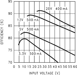
|
